-
December 13, 2024
Cloud-based LaTeX collaboration with Calkit and GitHub Codespaces
Research projects often involve producing some sort of LaTeX document, e.g., a conference paper, slide deck, journal article, proposal, or multiple of each. Collaborating on one of these can be painful, though there are web- or cloud-based tools to help, the most popular of which is probably Overleaf. Overleaf is pretty neat, but the free version is quite limited in terms of versioning, collaboration, and offline editing. Most importantly, I feel like it’s only really suited to pure writing projects. Research projects involve writing for sure, but they also involve (often iteratively) collecting and analyzing data, running simulations, creating figures, etc., which are outside Overleaf’s scope.
Calkit on the other hand is a research project framework encompassing all of the above, including writing, and is built upon tools that can easily run both in the cloud and locally, on- or offline, for maximum flexibility. Here we’re going to focus doing everything in a web browser though. We’ll set up a collaborative LaTeX editing environment with Calkit and GitHub Codespaces, a container-based virtual machine service.
Disclosure: There is a paid aspect of the Calkit Cloud, which I manage, to help with the costs of running the system, and to prevent users for pushing up unreasonable amounts of data. However, the software is open source and there is a free plan that provides more than enough storage to do what we’ll do here.
Create the project
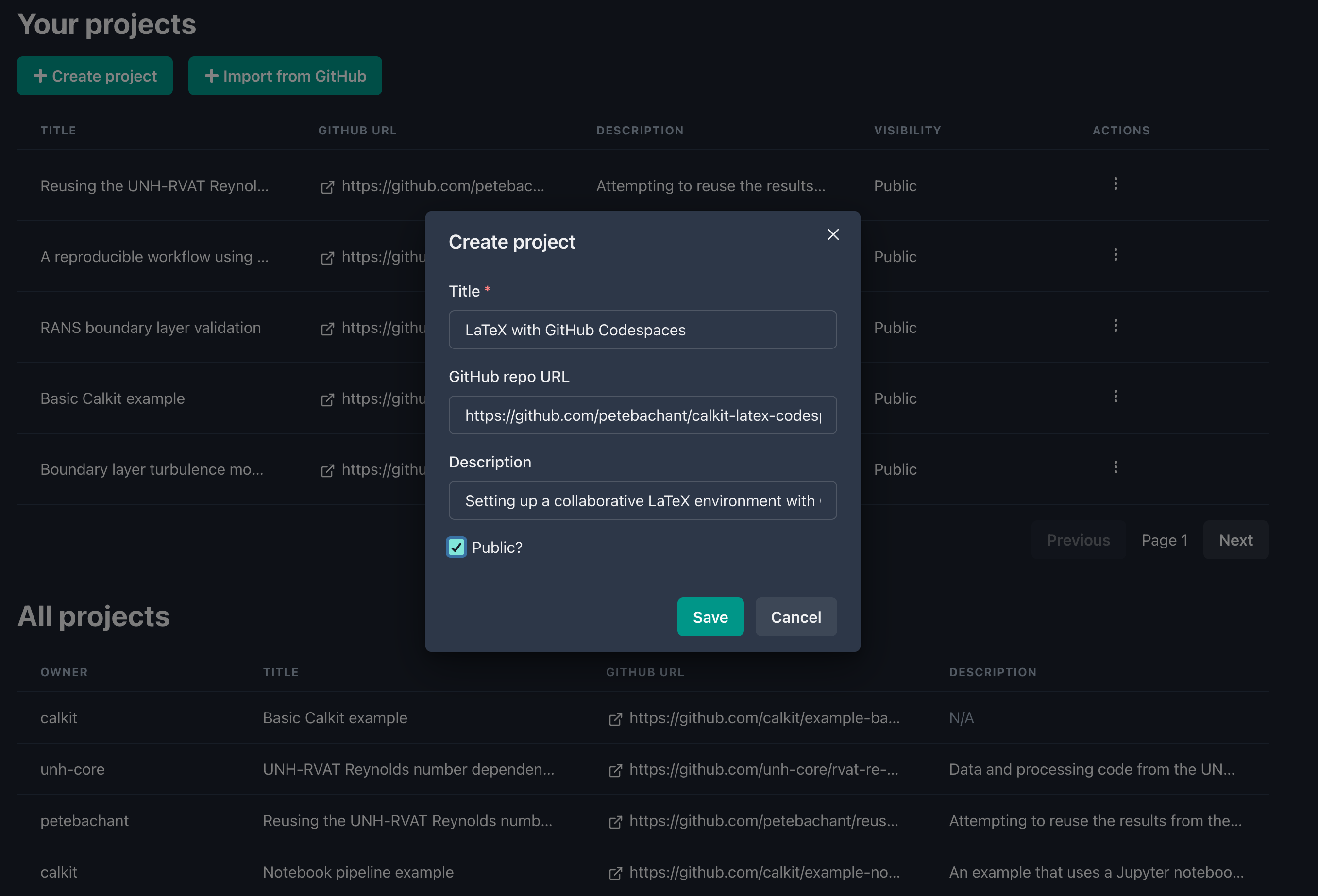
In order to follow along, you’ll need a GitHub account, so if you don’t have one, sign up for free. Then head to calkit.io, sign in with GitHub, and click the “create project” button. Upon submitting, Calkit will create a new GitHub repository for us, setup DVC (Data Version Control) inside it, and create a so-called “dev container” configuration from which we can spin up our GitHub Codespace and start working.
Add a new publication to the project
Click the quick action link on the project homepage to “create a new publication from a template.” In the dialog, select the
latex/articletemplate, and fill in the rest of the required information. This will add a LaTeX article to our repo and a build stage to our DVC pipeline, which will automatically create a TeX Live Docker environment to build the document. Here we’ll create the document in a new folder calledpaper: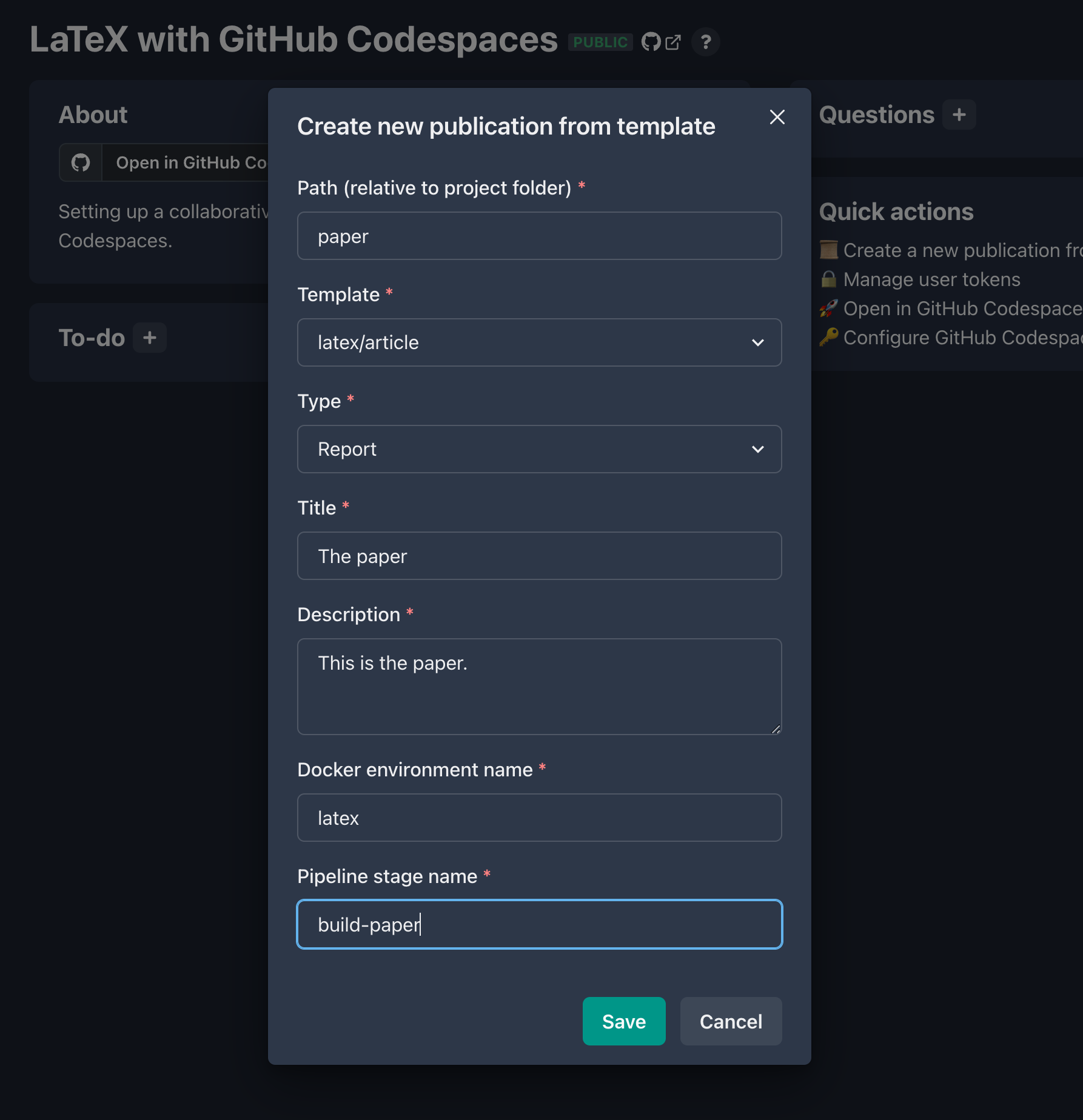
Keep in mind that you’ll be able add different LaTeX style and config files later on if the generic article template doesn’t suit your needs. Also, if you have suggestions for templates you think should be included, drop a note in a new GitHub issue.
Create the Codespace
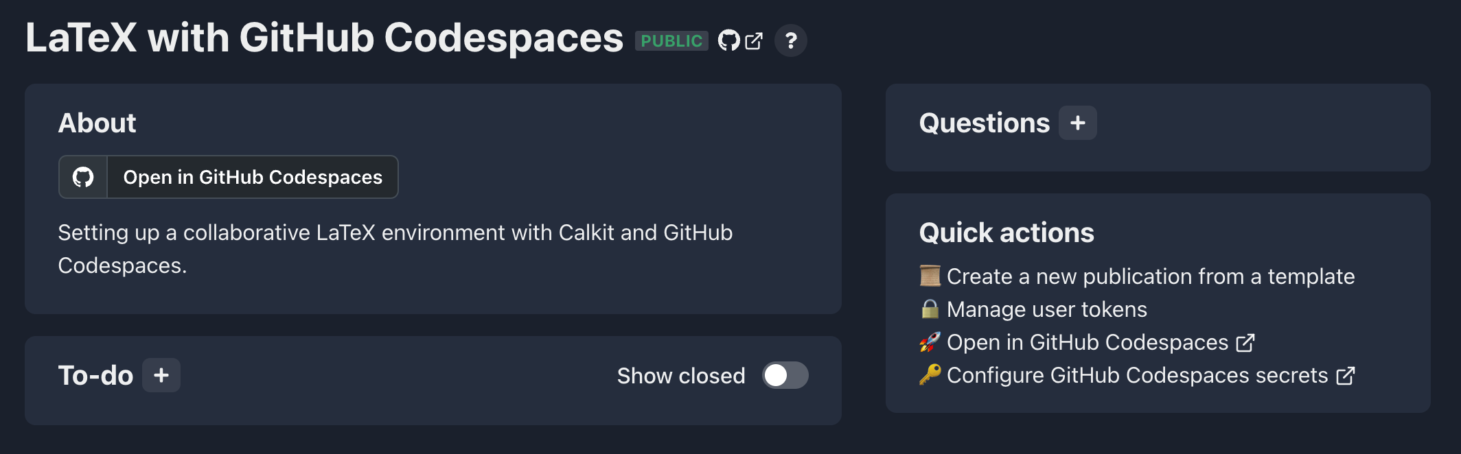
In order to push artifacts like PDFs up to the Calkit Cloud’s DVC remote, we will need a token and we’ll need to set it as a secret for the Codespace. On the Calkit project homepage you’ll see a link in the quick actions section for managing user tokens.
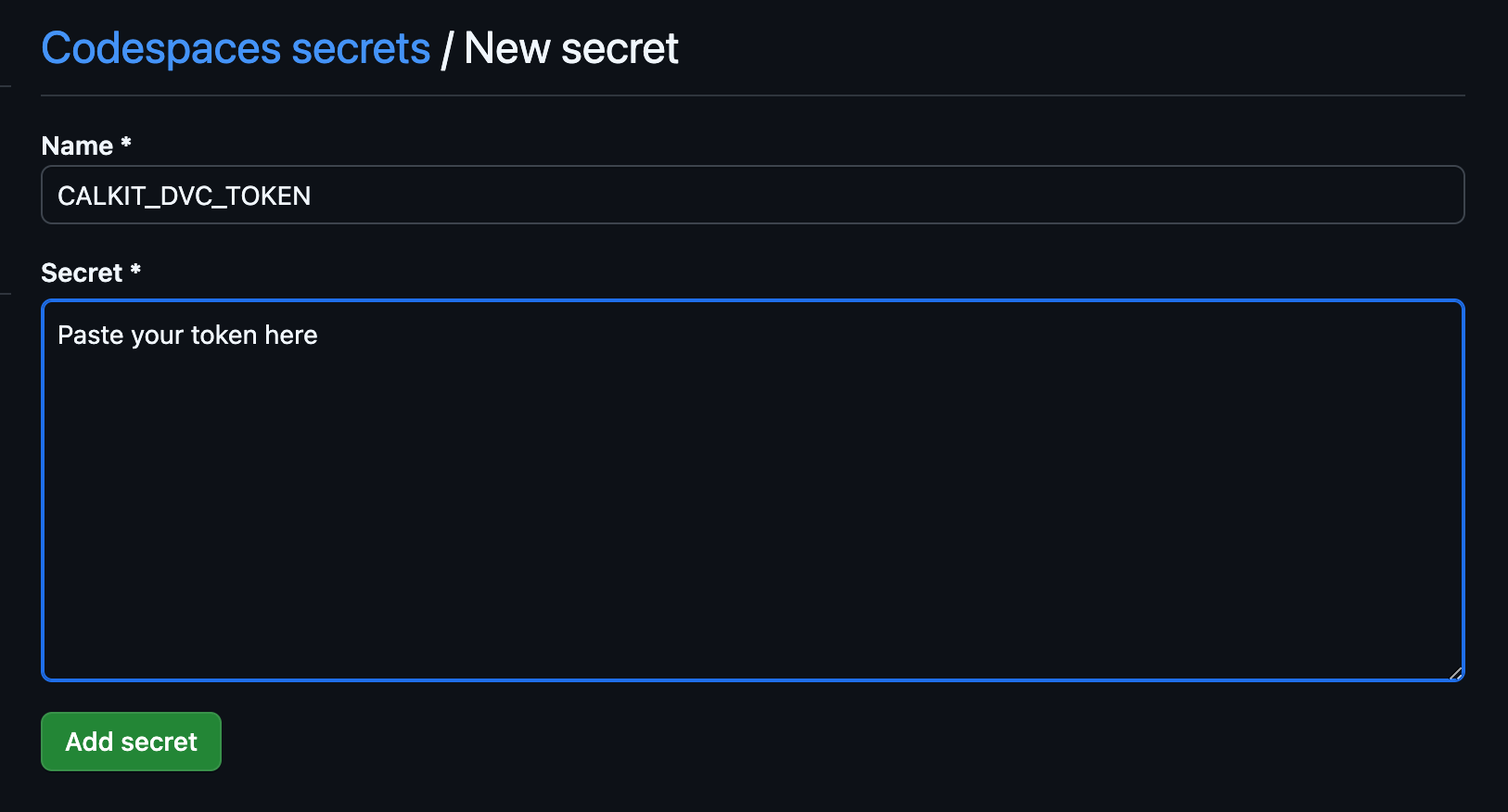
Head over there and create one, selecting “DVC” as the purpose. Save this in a password manager if you have one, then head back to the project homepage and click the quick action link to configure GitHub Codespaces secrets for the project. Create a secret called
CALKIT_DVC_TOKENand paste in the token.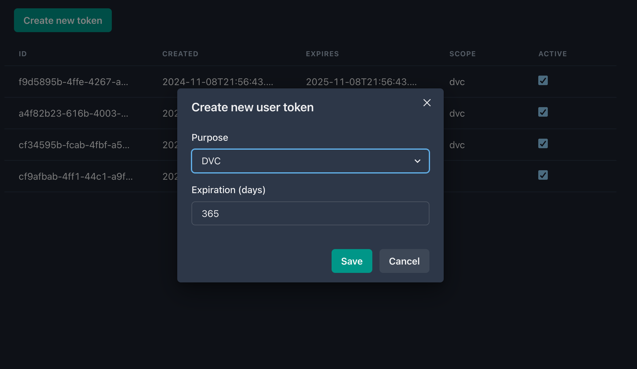
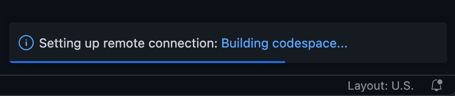
Next, from the project homepage, click “Open in GitHub Codespaces.” Alternatively, if you haven’t created your own project, you can create your own Codespace in mine.
Once created, we’ll see an in-browser Visual Studio Code (VS Code) editor, which will have access to our project repository and will be able to compile the LaTeX document. Consider this your very own Linux virtual machine in the cloud for working on this project. You can update settings, add extensions, etc. You have total control over it. Note that GitHub does charge for Codespaces, but the free plan limits are reasonably generous. It’s also fairly easy to run the same dev container configuration locally in in VS Code.
It might take few minutes to start up the first time as the Codespace is created, so go grab a coffee or take the dog for a walk.
Edit and build the document
After the Codespace is built and ready, we can open up
paper/paper.texand start writing.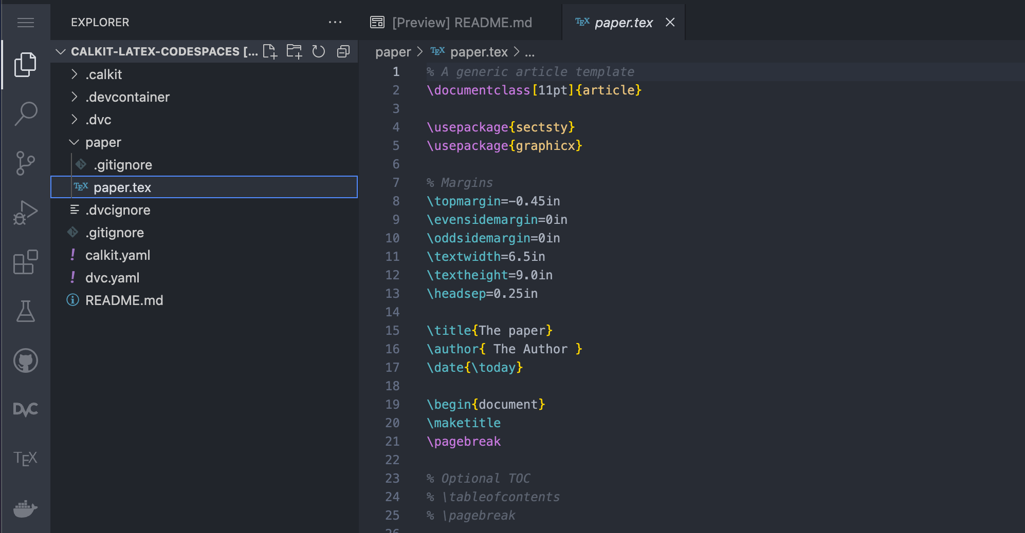
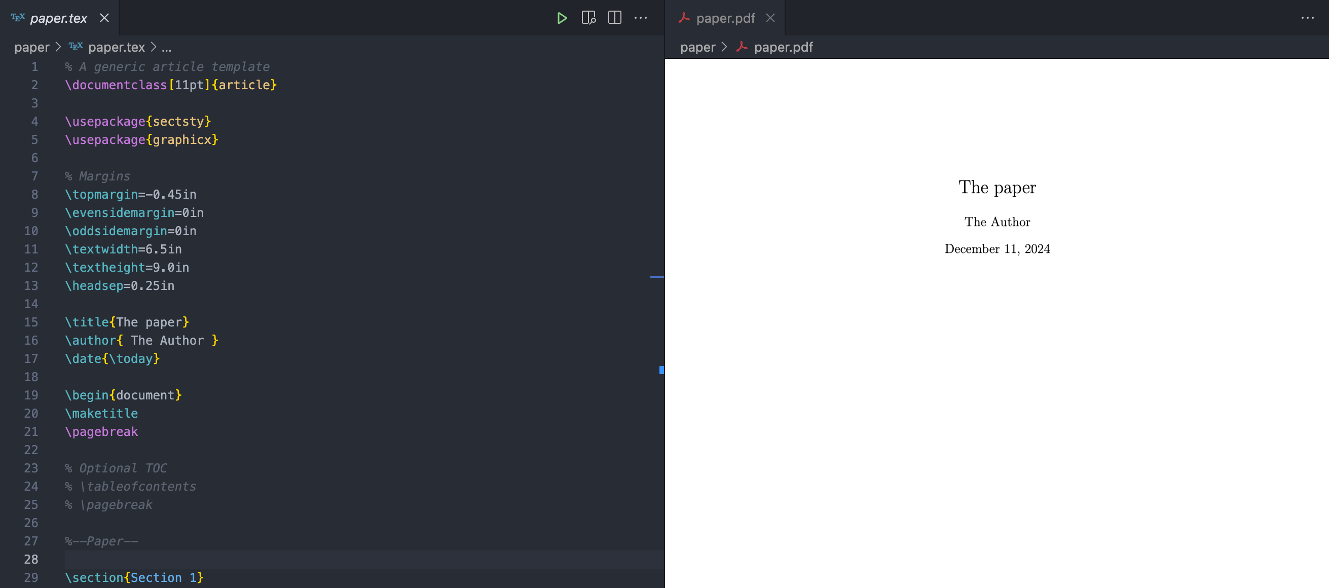
If you look in the upper right hand corner of the editor panel, you’ll see a play button icon added by the LaTeX Workshop extension. Clicking that will rebuild the document. Just to the right of that button is one that will open the PDF in split window, which will refresh on each build.
Note that the play button will run the entire pipeline (like calling
calkit runfrom a terminal,) not just the paper build stage, so we can add more stages later, e.g., for creating figures, or even another LaTeX document, and everything will be kept up-to-date as needed. This is a major difference between this workflow and that of a typical LaTeX editor, i.e., that the entire project is treated holistically. So for example, there’s no need to worry about if you forgot to rerun the paper build after tweaking a figure—it’s all one pipeline. See this project for an example, and check out the DVC stage documentation for more details on how to build and manage a pipeline.Break lines in a Git-friendly way
This advice is not unique to cloud-based editing, but it’s worth mentioning anyway. When writing documents that will be versioned with Git, make sure to break lines properly by splitting them at punctuation or otherwise breaking into one logical phrase per line. This will help when viewing differences between versions and proposed changes from collaborators. If you write paragraphs as one long line and let them “soft wrap,” it will be a little more difficult.
So, instead of writing something like:
This is a very nice paragraph. It consists of many sentences, which make up the paragraph.write:
This is a very nice paragraph. It consists of many sentences, which make up the paragraph.The compiled document will look the same.
Commit and sync changes
For better or for worse, working with Git/GitHub is different from other systems like Google Docs, Overleaf, or Dropbox. Rather than syncing our files automatically, we need to deliberately “commit” changes to create a snapshot and then sync or “push” them to the cloud. This can be a stumbling block when first getting started, but one major benefit is that it makes one stop and think about how to describe a given set of changes. Another benefit is that every snapshot will be available forever, so if you create lots of them, you’ll never lose work. In a weird mood and ruined a paragraph that read well yesterday? Easy fix—just revert the changes.
The VS Code interface has a built-in graphical tool for working with Git and GitHub, which can make things a little easier compared to learning the command-line interface (CLI.) If we make some changes to
paper.tex, we can see a blue notification dot next to the source control icon in the left sidebar. In this view we can see there are two files that have been changed,paper.texanddvc.lock, the latter of which is a file DVC creates to keep track of the pipeline, and shows up in the “Staged Changes” list, a list of files that would be added to a snapshot if we were to create a commit right now.We want to save the changes both this file and
paper.texin one commit, so let’s stage the changes topaper.tex, write a commit message, and click commit.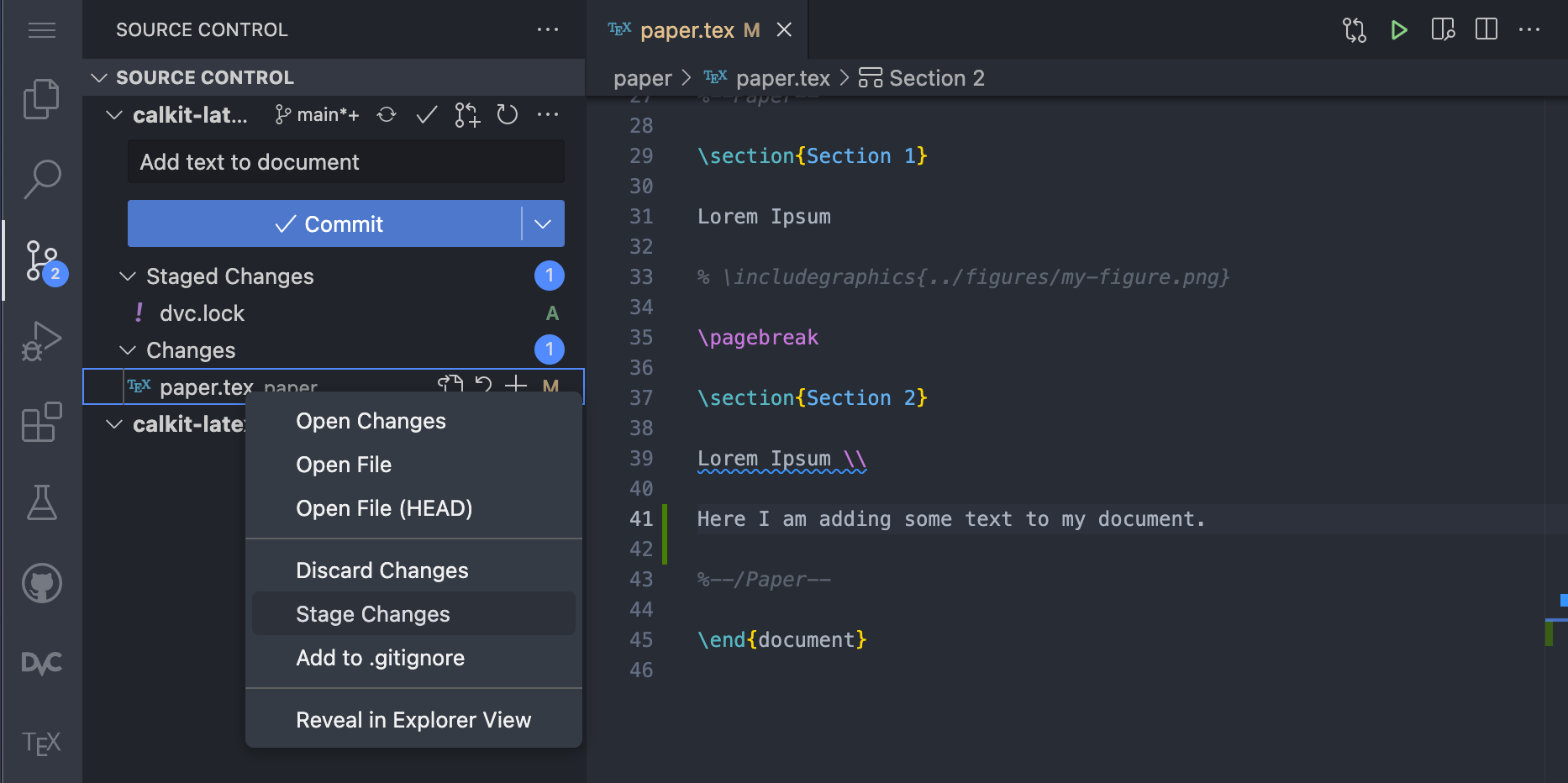
After committing we’ll see a button to sync the changes with the cloud, which we can go ahead and click. This will first pull from and then push our commits up to GitHub, which our collaborators will then be able to pull into their own workspaces.
Push the PDF to the cloud
The default behavior of DVC is to not save pipeline outputs like our compiled PDF to Git, but instead commit them to DVC, since Git is not particularly good at handling large and/or binary files. The Calkit Cloud serves as a “DVC remote” for us to push these artifacts to back them up and make them available to others with access to the project.
If we go down to the terminal and run
calkit push, we’ll push our DVC artifacts (just the PDF at this point) up to the cloud as well, which will make our PDF visible in the publications section of the project homepage. Note thatcalkit pushwill also send the Git changes to GitHub, completely backing up the project.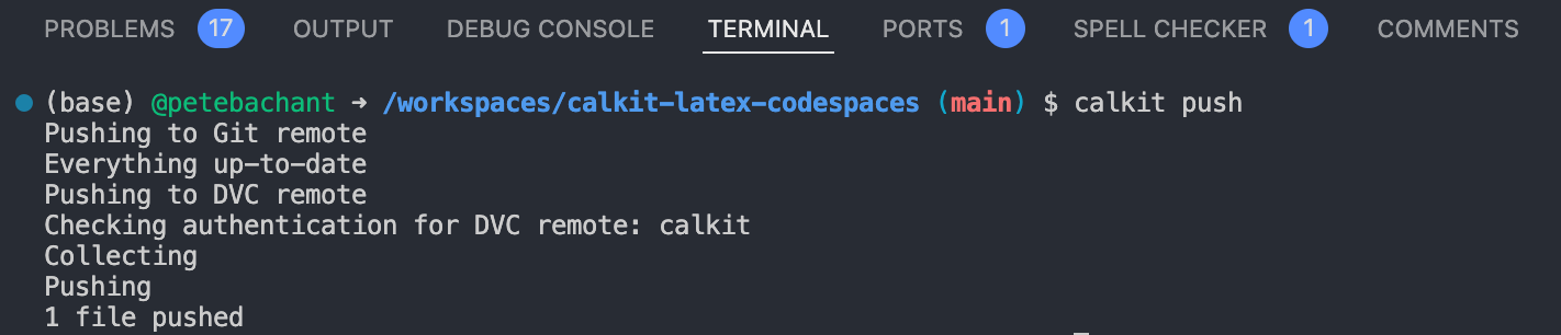
Later on, if you end up adding things like large data files for analysis, or even photos and videos from an experiment, these can also be versioned with DVC and backed up in the cloud.
Collaborate concurrently
What we’ve seen so far is mostly an individual’s workflow. But what if we have multiple people working on the document at the same time? Other cloud-based systems like Google Docs and Overleaf allow multiple users to edit a file simultaneously, continuously saving behind the scenes. My personal opinion is that concurrent collaborative editing is usually not that helpful, at least not on the same paragraph(s). However, if you really like the Google Docs experience, you can setup the Codespace for live collaboration. Otherwise, collaborators can create their own Codespaces from the same configuration just like we created ours.
Git is actually quite good at automatically merging changes together, but typically you’ll want to make sure no two people are working on the same lines of text at the same time. You’ll need to communicate a little more with your collaborators so you don’t step on each other’s toes and end up with merge conflicts, which require manual fixes. You could simply send your team a Slack message letting them know you’re working on the doc, or a given section, and avoid conflicts that way. You could split up the work by paragraph or section, and even use LaTeX
\inputcommands in the main.texfile to allow each collaborator to work on their own file.Git can also create different branches of the repo in order to merge them together at a later time, optionally via GitHub pull requests, which can allow the team to review proposed changes before they’re incorporated. However, for many projects, it will be easier to have all collaborators simply commit to the main branch and continue to clean things up as you go. If commits are kept small with descriptive messages, this will be even easier. Also, be sure to run
git pulloften, either from the UI or from the terminal, so you don’t miss out on others’ changes.Manage the project with GitHub issues
Another important aspect of collaborative writing is reviewing and discussing the work. I recommend using GitHub issues as a place to create to-do items or tasks and discuss them, which is particularly helpful for team members who are mostly reviewing rather thant writing.
One approach to creating issues is to Download the latest PDF of the document, add comments, and attach the marked up PDF to a new GitHub issue. A variant of this is printing it out and scanning the version with red pen all over it.
Another approach is to create issues from within VS Code. In the
.texfile, you can highlight some text and create a GitHub issue from it with the “Create Issue From Selection” command. Open up the command palette withctrl/cmd+shift+pand start typing “issue from selection”. The command should show up at the top of the list.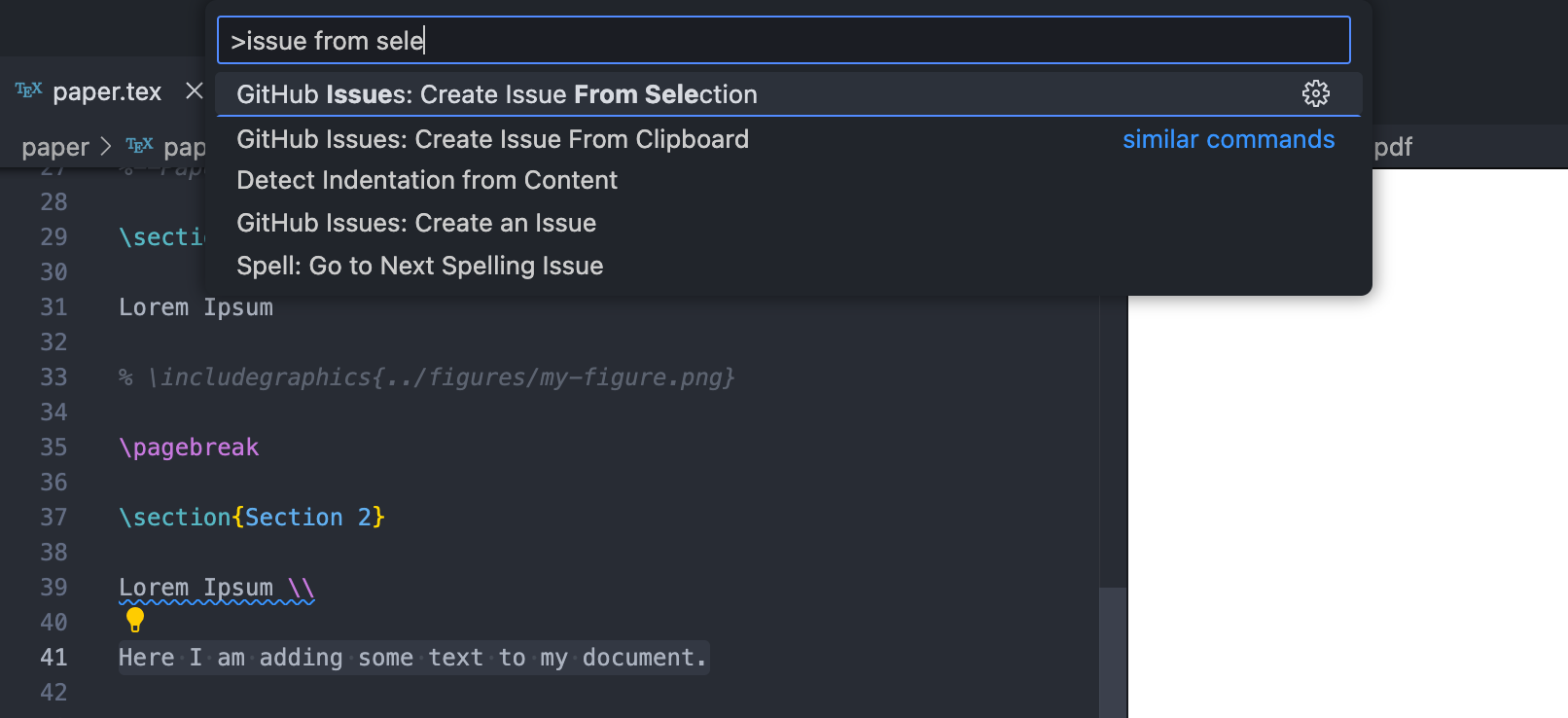
After you create a new issue, click the GitHub icon in the left pane and look through the recent issues. You can right click on an issue and select “Go to Linked Code” to do just that.
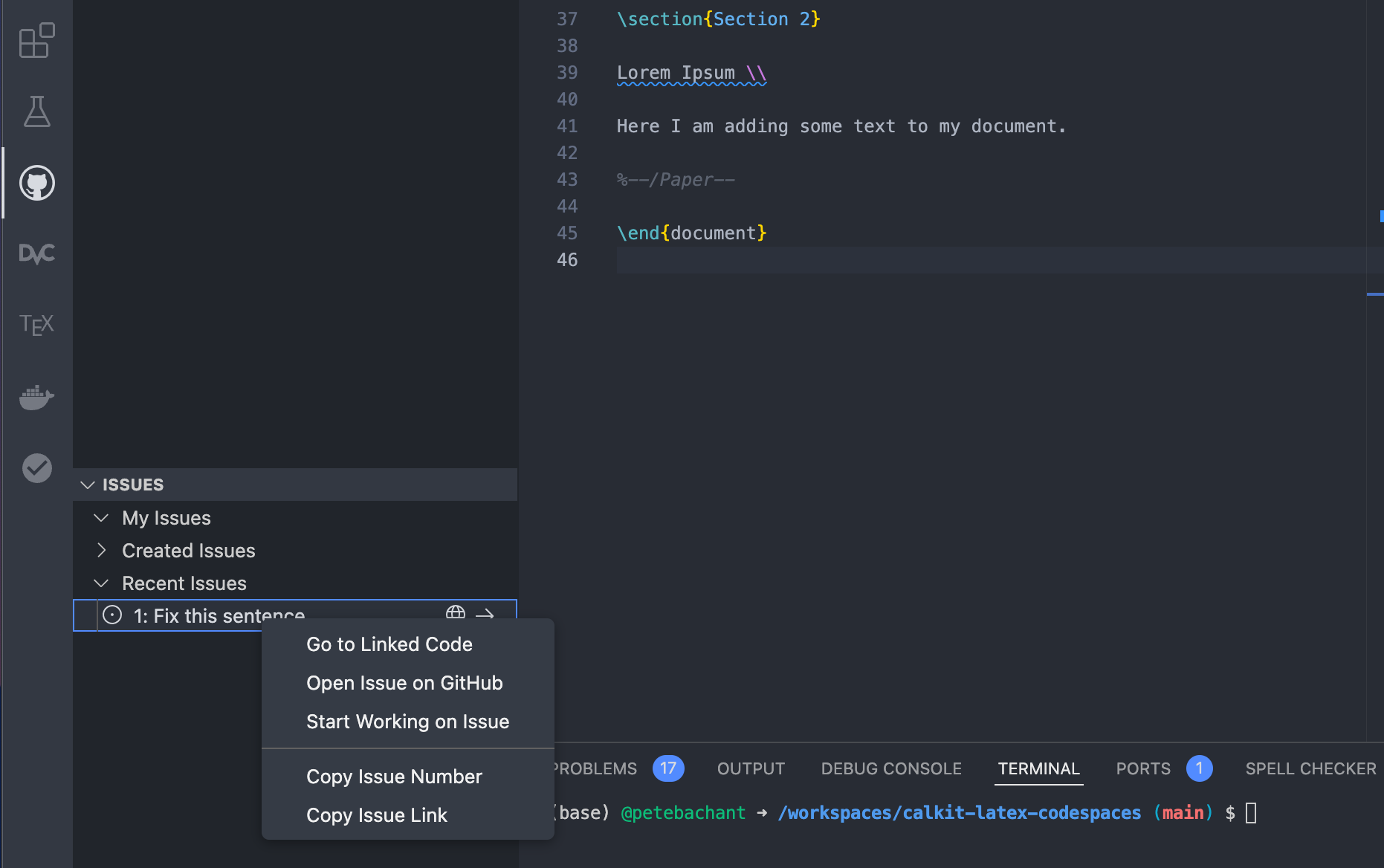
If you make a commit that addresses a given issue, you can include “fixes #5” or “resolves #5” in the commit message, referencing the issue number, and GitHub will automatically close it.
For complex cases with lots of tasks and team members, GitHub projects is a nice solution, allowing you to put your tasks into a Kanban board or table, prioritize them, assess their effort level, and more. Also note that these GitHub issues will also show up in the “To-do” section on the Calkit project homepage, and can be created and closed from there as well.
Conclusions
Here we set up a way to collaborate on a LaTeX document in the cloud using GitHub Codespaces. The process was a little more involved compared to using a dedicated LaTeX web app like Overleaf, but our assumption was that this document is part of a larger research project that involves more than just writing. Because the document is integrated into a Calkit project, it is built as a stage in a DVC pipeline, which can later be extended to include other computing tasks like creating datasets, processing them, making figures, and more.
We also went over some tactics to help with version control, concurrent editing, and project management. Though we did everything in a web browser, this setup is totally portable. We’ll be able to work equally well locally as we can in the cloud, allowing anyone to reproduce the outputs anywhere.
Have you struggled to collaborate on LaTeX documents with your team before? I’d be interested to hear your story, so feel free to send me an email.
-
December 06, 2024
I failed to reproduce my own results from a decade ago
My former PhD advisor emailed me recently regarding a grad student interested in using some experimental data we had collected a decade ago to validate some simulations. The repo from the experiment was still up on GitHub, so I assumed that would be easy, but I was wrong.
I had left instructions in the README for getting started and regenerating the figures:
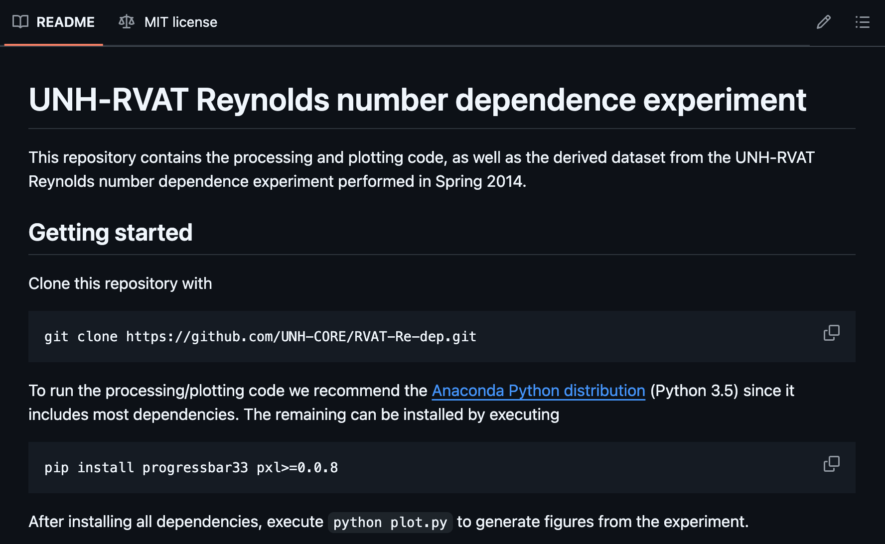
So I gave it a try. These days I have Mambaforge installed on my machine instead of Anaconda, but the ecosystems are largely compatible with each other, so I figured there was a decent chance this would work. The
pip installcommands worked fine, so I tried runningpython plot.py, but that actually doesn’t do anything without some additional options (bad documentation, me-from-the-past!) After running the correct command, this was the result: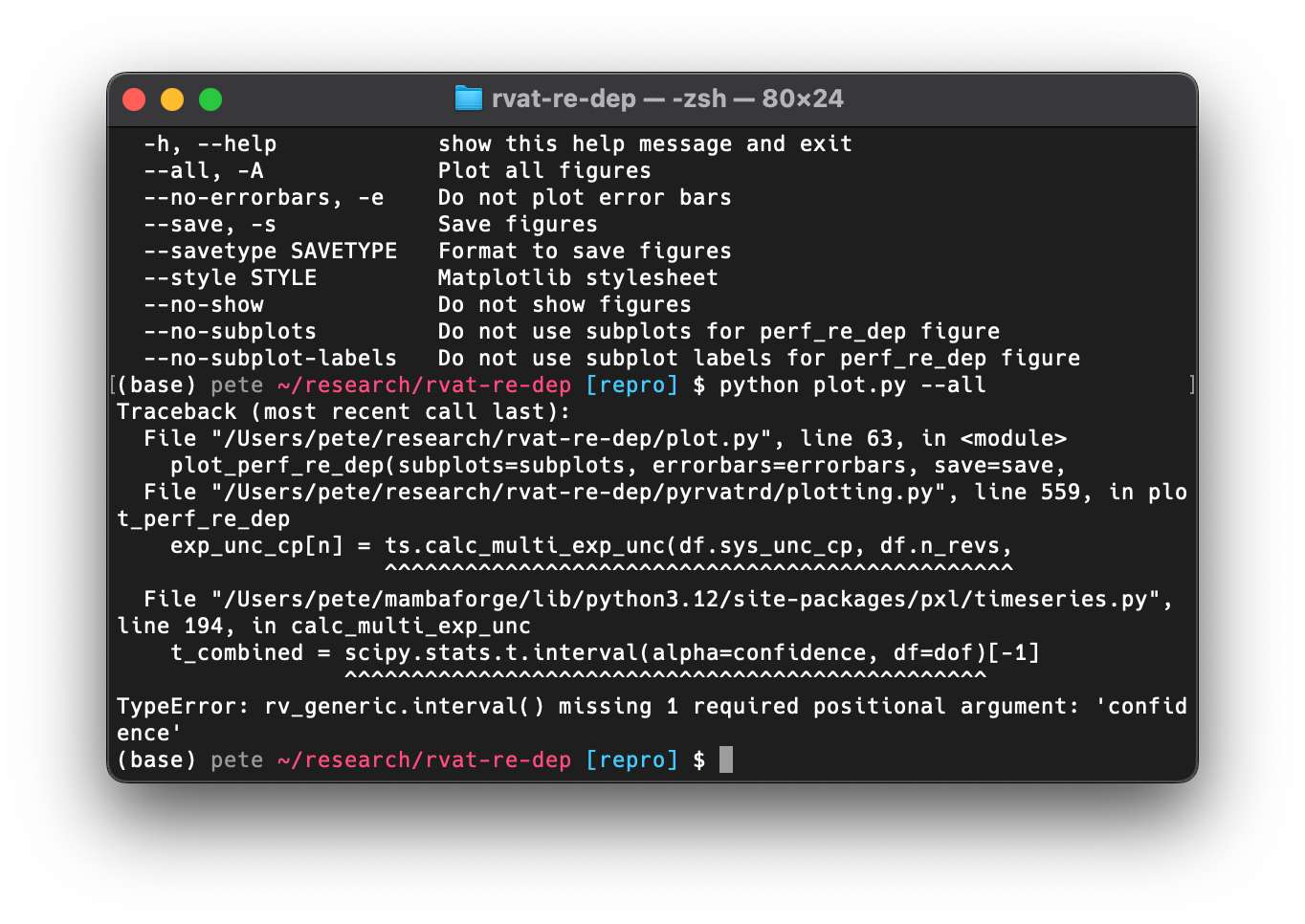
As we can see, this failed because the interface to the
scipy.stats.t.intervalfunction had changed since the version I was using back then. This isn’t necessarily surprising after 10+ years, but it puts us at a crossroads. We would either need to adapt the code for newer dependencies or attempt to reproduce the environment in which it ran before.But let’s take a step back and ask why we would want to do this at all. I can think of two reasons:
- Reproducing the results can help ensure there are no mistakes,
or that the outputs (figures) genuinely reflect the inputs (data)
and processes (code). There is a chance that I updated the code at some
point but never reran
plot.py, making the figures out-of-date. - We want to produce a slight variant of one or more figures, adding the results from a simulation for the purposes of validation.
These can be categorized as reproducibility and reusability, respectively, and the grad student’s request was clearly concerned with the latter. However, I wanted to explore both.
Attempting to reproduce the old environment
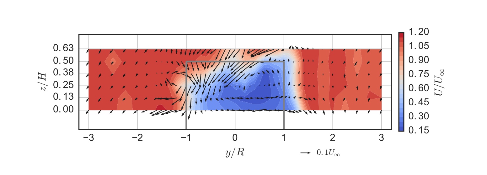
Before we start, let’s pick a figure from the original paper to focus on reproducing. For this I chose one that’s relatively complex. It shows out-of-plane mean velocity in a turbine wake as contours and in-plane mean velocity as vector arrows, and includes an outline of the turbine’s projected area. It uses LaTeX for the axis labels, and is set to match the true aspect ratio of the measurement plane. Here’s what it looked like published:
I left myself some incomplete instructions in that README for reproducing the old environment: Install a version of Anaconda that uses Python 3.5 and
pip installtwo additional packages. Again, bad documentation, me-from-the-past! Given that I already havecondainstalled, I figured I could generate a new environment with Python 3.5 and take it from there.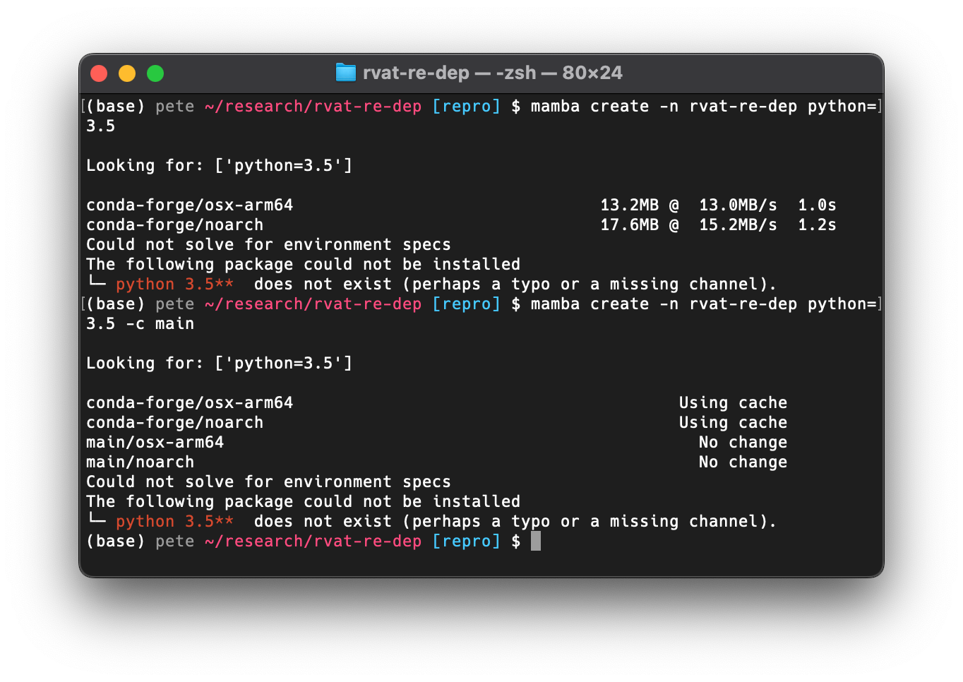
No luck, however. Python 3.5 is not available in the
conda-forgeormainchannels any longer, at least not for my MacBook’s ARM processor.The next logical option was Docker. There are some old Anaconda Docker images up on Docker Hub, so I thought maybe I could use one of those. The versions don’t correspond to Python versions, however, so I had to search though the Anaconda release notes to find which version I wanted. Anaconda 2.4.0, released on November 2, 2015, was the first version to come with Python 3.5, and that version is available on Docker Hub, so I tried to spin up an interactive container:
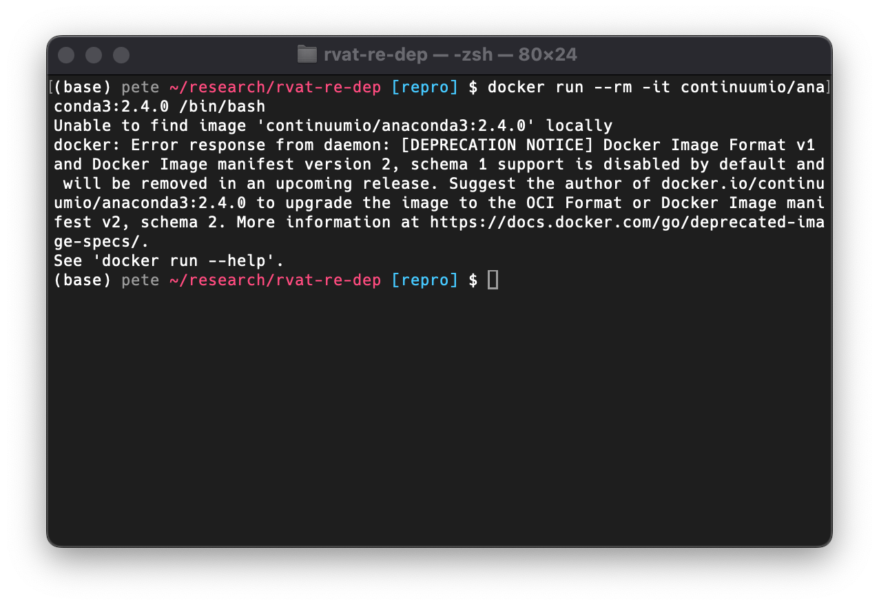
To my surprise, this failed. Apparently there was a change in Docker image format at some point and these types are no longer supported. So I searched for the newest Anaconda version with Python 3.5, which was Anaconda 4.2.0, and luckily the image was in the correct format.
At this point I needed to create a new image derived from that one that installed the additional dependencies with
pip. So I created a new Docker environment for the project and added a build stage to a fresh DVC pipeline with Calkit (a tool I’ve been working on inspired by situations like these):calkit new docker-env \ --name main \ --image rvat-re-dep \ --from continuumio/anaconda3:4.2.0 \ --description "A custom Python 3.5 environment" \ --stage build-dockerIn this case, the automatically-generated
Dockerfiledidn’t yet have everything we needed, but it was a start.Simply adding the
pip installinstructions from the README resulted in SSL verification and dependency resolution errors. After some Googling and trial-and-error, I was able to get things installed in the image by adding this command:RUN pip install \ --trusted-host pypi.org \ --trusted-host pypi.python.org \ --trusted-host files.pythonhosted.org \ --no-cache-dir \ progressbar33 \ seaborn==0.7.0 \ pxl==0.0.9 \ --no-depsNote that I had to pin the
seabornversion sincepxlwould install a newer version, which would install a newer version ofpandas, which would fail, hence the--no-depsoption.I also had to set the default Matplotlib backend with:
env MPLBACKEND=Aggsince PyQt4 was apparently missing and Matplotlib was trying to import it by default.
After running the pipeline to build the Docker image, I ran the plotting script in that environment with:
calkit runenv -n main -- python plot.py all_meancontquiv --saveLet’s take a look at the newly-created figure and compare with the original published version:
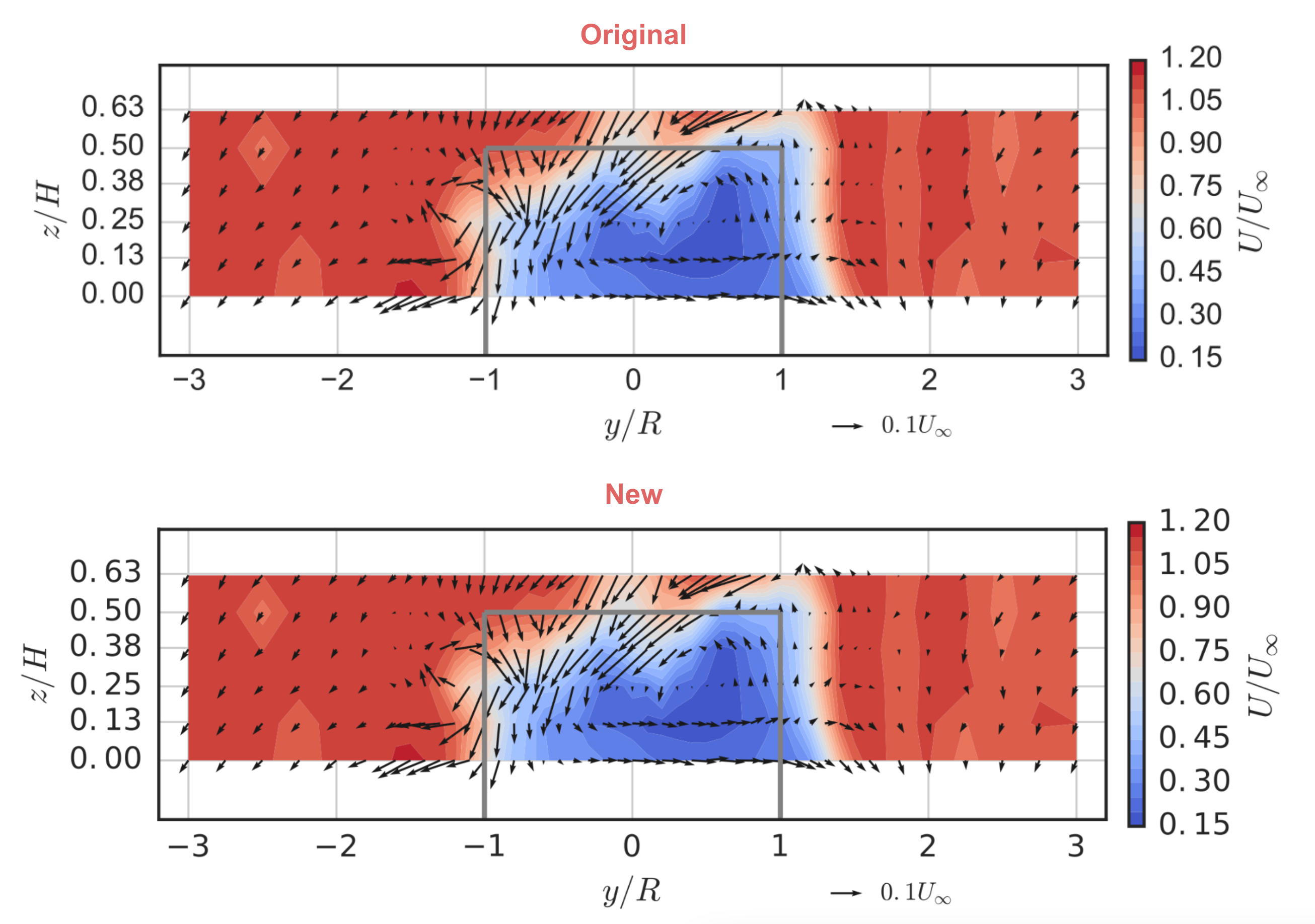
If you look closely you’ll notice the font for the tick labels is slightly different from that in the original. We could go further and try to build the necessary font into the Docker image, but I’m going to call this a win for now. It took some hunting and finagling, but we reproduced the figure.
But what about reusability?
Looking back at project repo’s README we can see I said absolutely nothing about how one could reuse the materials in a different project. To be fair, at the time the main purpose of open sourcing these materials was to open source the materials. Even that is still somewhat uncommon for research projects, and I do think it’s a good goal in and of itself. However, if we want to ensure our work produces the largest possible impact, we should do a little “product management” and spend some time thinking about how others can derive value from any of the materials, not just the paper we wrote.
I actually used this dataset in a later paper validating some CFD simulations, the repo for which is also on GitHub. Looking in there, the value that this project’s repo provided was:
- CSV files containing aggregated or reduced data.
- A Python package that made it possible to:
- recreate the Matplotlib figures so we didn’t need to copy/paste them,
- instantiate a
WakeMapPython class that computed various gradients to aid in computing wake recovery quantities to compare against simulation, - inspect the code that generated complex figures so it could be adapted for plotting the CFD results.
Items 2.1 and 2.2 were actually not that easy to do, since the Python package was not installable. In the follow-on project I had to add the folder to
sys.pathto import the package, and since it used relative paths, I had to make the new code change directories in order to load the correct data. These are both not too difficult to fix though.First, we can make the Python package installable by adding a
pyproject.tomlfile. Then we can switch to using absolute paths so the data loading and plotting functions can be called from outside.Updating the code for the newer dependencies was not too difficult based on the tracebacks. After getting things running in a more modern Python 3.12 environment, I exported a “lock” file describing all versions used the last time it successfully ran. This is much more descriptive than “Anaconda with Python 3.5.”
Finally, I wanted to add some documentation explaining how to reuse this code and data. I ended up adding two sections to the README: one for reproducing the results and one for reusing the results. I also created an example project reusing this dataset by including it as a Git submodule, which you can also view up on GitHub. Doing this is a good way to put yourself in the users’ shoes and can reveal stumbling blocks. It also gives users a template to copy if they would find that helpful.
It’s important to note here that it’s impossible to predict how others might derive value from these materials, and that’s okay. Take some educated guesses, put it out there, and see what happens. Maybe you’ll want to iterate later, like I’ve done here. That’s much better than not sharing at all.
Conclusions
There are a few takeaways from this exercise. First off, reproducibility is hard, even with all of the code and data available. Software and hardware continue to evolve, and just because the code “runs on my machine” today, doesn’t mean it will a few years (or decades) down the road. On the other hand, maybe reproducibility should have a practical expiration date anyway, since it’s mostly useful around the time of publication to help avoid mistakes and potentially speed up peer review.
Another important but obvious point is that documentation is crucial. Simply providing the code and data without documentation is better than nothing, and many papers don’t even go that far, but we really should go further. Every project should fully describe the steps to reproduce the outputs, and there should be as few steps as possible. This can be beneficial while the project is in progress as well, especially if we have collaborators.
Lastly, reproducibility is not the same thing as reusability. Researchers should do some product management and attempt to maximize the value they can deliver. The “product” of a given research project could be a simple formula for hand calculations, but these days the valuable products will likely include datasets and software.
Publishing a paper with an “in-house” code may be good for your career (for now anyway,) but if your discoveries are useless without a computer program to calculate predictions, the effort others will need to expend to get value from your work will be unnecessarily high, and therefore some potential impact will be unrealized. “It’s not documented well enough” is not a valid excuse either. Like with reproducibility, even if we haven’t molded our research products into the most user-friendly form possible, we should still share all of the relevant materials, so long as it’s not harmful to someone else to do so.
- Reproducing the results can help ensure there are no mistakes,
or that the outputs (figures) genuinely reflect the inputs (data)
and processes (code). There is a chance that I updated the code at some
point but never reran